- Author Nora Macey macey@family-relation.com.
- Public 2023-12-16 10:17.
- Last modified 2025-01-23 08:47.
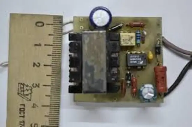
Switching power supplies are of interest in amateur radio circles. Increasingly, it is to them that the gaze of radio amateurs turns, since such devices have a number of advantages over traditional transformer devices.

DIY switching power supplies are assembled using microcircuits with the desired parameters. Their selection is made according to special radio technical tables. Switching power supplies are developed on printed circuit boards, which are made of one-sided fiberglass. Based on the schematic diagram of the product, a drawing of current-carrying paths for a printed circuit board is being developed. For transistors, heatsinks will be needed (if necessary, they can be made from an aluminum plate).
Features of the manufacture of a transformer
The step-down transformer is wound on a ferrite ring, the brand of which is M200MN. The primary winding contains an insulated wire of the MGTF 0, 7 brand. The secondary winding is made of PEV-1 wire (folded in half). An insulating layer (PTFE tape) is located between them. In the middle part of the secondary winding there is a branch for powering the microcircuit. The wires are insulated with a double layer of fluoroplastic tape.
Used radio parts
For the input choke, you can use ready-made parts that are installed, for example, in computer power supplies. The capacitor is selected so that the ratio of capacitance to power is 1: 1. The rectifier is made of a diode bridge with a low operating frequency. Such a product can show an output current of up to 3 amperes. The switching power supplies include transistor switches. Their selection is carried out according to the necessary parameters. In order to provide the required temperature regime, they must have cooling radiators (for heat removal). Switching power supplies are manufactured with output parts consisting of chokes with ferrite cylinders with a length of 40 mm and a diameter of 3 mm. The winding of the turns is carried out tightly, for which the PEV-1 wire is used.
Features of the assembly of a switching power supply
The power supply is assembled on a pre-prepared board. After the soldering is completed, it is required to check the reliability of the installation of radio components, the condition of the contacts between them and the current-carrying tracks. Leaks and traces of solder are cleared from the board and radio components, due to which a short circuit is possible. Switching power supplies (during testing) must be loaded with a current-limiting resistor. A conventional 60 W incandescent lamp can also be used. Its short-term inclusion in operation will signal the correct assembly of the device.


