- Author Nora Macey [email protected].
- Public 2023-12-16 10:17.
- Last modified 2025-01-23 08:48.
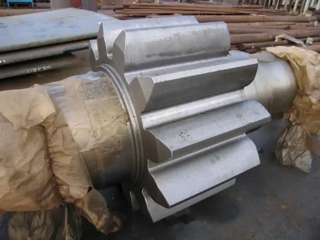
Novice designers in the production of a mater, as a rule, are given a test task to draw a shaft. It is not the most difficult, but many cannot cope with it.

Instructions
Step 1
In order to draw a shaft, it is necessary to have a visual image of it with the indicated dimensions. Draw the drawing in three secant planes A, B and C.
First of all, draw the main view of the shaft, observing the 1: 1 scale on the A3 format in the direction of arrow A. On one of the cylindrical journals of the shaft, provide for the presence of a special groove, which will be required for the exit of the grinding wheel. For her, make a detail. Set the dimensions and shape of the grooves in accordance with GOST 8820-80. The defining dimension will be directly the diameter of the shaft on which the groove is located.
Step 2
In order to subsequently assemble the product in a production environment, perform chamfers on the ends of the parts. On one end of the shaft, draw a 45 ° chamfer and mark, for example, 2 x 45 °.
Step 3
Then make local incisions. This must be done to size and define the internal structure.
To transmit torque to the gear from the shaft, use a key that fits directly into the keyway. We select the dimensions of the keyway according to GOST 23360-78. They depend on the diameter of the shaft itself. Apply a local top view and cross-section to clarify the shape of the groove.
Step 4
Make three sections. On the continuation of the trail of the cutting plane, place the section with the plane A. Make the section with the plane B in a free space of the drawing. And, finally, the section by plane B will be in the projection connection.

Step 5
Apply the dimensions required to manufacture the part. Perform the designation of images in accordance with GOST 2.305-68.
Step 6
In the “material” column of the title block, indicate GOST and the grade of material from which the shaft will be made.
Step 7
In technical drawing, not only reproduce the visible form of the depicted object, but also keep it under constant control of a special direction of thinking. In other words, do not forget and consciously apply the features of constructions that are inherent in axonometric projections. We are talking about the location of axonometric axes, distortion indicators, and more.
Step 8
And one more essential point: remember the direction of view for the choice of the main view and the position of the split planes.
By putting into practice these simple and consistent tips, you can easily cope with the task in front of you and draw the shaft without any difficulty.


